Rotating machinery rarely fails without a cause, though its earliest warning signs can be easy to overlook. A faint bearing whine, a rising vibration reading, or a small oil leak may signal a developing problem. Sometimes, the change seems minor. Under continued load, however, minor changes can become costly shutdowns or safety concerns.
So, what are common failures in rotating machinery? This guide examines ten recurring problems, including bearing damage, misalignment, imbalance, lubrication failure, and seal leakage. It also considers issues such as looseness, overheating, corrosion, cavitation, and shaft or coupling damage. These problems can affect pumps, motors, fans, compressors, and other equipment, but their symptoms often overlap. A vibration increase alone does not prove imbalance; operating conditions and inspection findings matter.
Reliable diagnosis combines practical experience with evidence. Technicians may compare vibration trends, check lubricant condition, listen for unusual noise, and inspect alignment during planned maintenance. Manufacturer guidance and qualified engineering judgment should inform decisions, especially when equipment operates under demanding conditions. No single checklist can explain every failure. Real systems are imperfect, and maintenance records may be incomplete. That deserves attention, not guesswork. The overview that follows helps readers recognize common patterns, ask better questions, and investigate problems before they disrupt production.
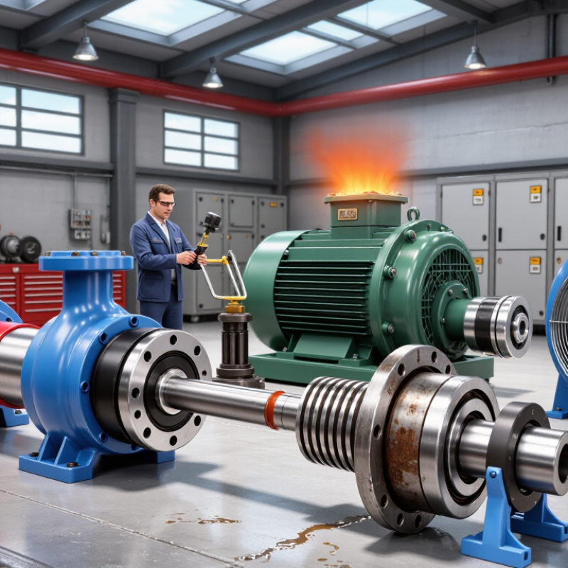
Rotating-machinery failures are easier to understand when grouped by where damage begins and how it develops. A useful framework separates faults into mechanical, lubrication-related, electrical, and process-induced categories. Mechanical faults include imbalance, misalignment, looseness, and bearing damage. They may produce rising vibration, unusual noise, or a changing temperature pattern. Small clues matter.
Lubrication failures include contamination, inadequate oil supply, and lubricant breakdown. A cloudy oil sample or a dry-looking bearing surface can offer early evidence, though neither proves the cause alone. Electrical faults, such as insulation deterioration or rotor problems, may show up as current irregularities or localized heating. Process-induced problems arise when flow, pressure, load, or temperature moves outside the machine’s intended range. Cavitation and repeated overload are common examples.
These groups can overlap. Misalignment may increase bearing load, while poor lubrication accelerates wear. That makes a single symptom an unreliable diagnosis. Compare vibration readings, operating conditions, maintenance records, and inspection findings before assigning a failure category. The classification is useful, but not perfect; real equipment rarely fails in tidy boxes.
How rotating-machinery failures are grouped
The bars show an illustrative relative-commonness index, not measured failure rates. Failure modes are grouped into lubrication, bearing, alignment, balance, mechanical looseness, gear, electrical, and process-related families. Actual frequency depends on machine type, operating conditions, and maintenance practices.
Vibration Failures: Imbalance, Misalignment, and Mechanical Looseness
A rotating machine often gives warning before it stops. A fan wheel with uneven dust can create a steady shake; a misaligned coupling may add heat and a repeating vibration pattern. Loose feet or foundation bolts can make the whole frame rattle. These faults can look similar, so one reading rarely tells the full story. The U.S. Department of Energy’s 2002 United States Industrial Electric Motor Systems Market Opportunities Assessment reports that motor-driven systems use about 69% of industrial electricity. That figure does not measure vibration losses, but it shows why small efficiency problems deserve attention.
A practical check starts with repeatable measurements at the same bearing locations and operating conditions. Compare vibration levels and frequency patterns with the machine’s baseline, then inspect coupling alignment, fasteners, and deposits on the rotor. A sudden change matters more than a number viewed alone. ISO 20816-3:2022 provides vibration evaluation guidance for certain industrial machines; its limits depend on machine type and installation. Don’t treat a standard as a substitute for diagnosis. I have seen readings mislead when load or speed changed between checks.
Tips: Record speed, load, sensor position, and temperature with each reading. Recheck after cleaning or tightening. If the vibration remains, investigate alignment and balance before replacing parts. Small details get missed. That is worth admitting.
| Failure mode | Typical vibration clues | Common contributing factors | Useful checks | Typical corrective action |
|---|---|---|---|---|
| 1. Rotor imbalance | Often a strong radial component at running speed (1×); amplitude may rise with speed. | Uneven mass distribution, material buildup, erosion, or a missing balance weight. | Compare radial readings at bearing locations; inspect the rotor and review phase data. | Remove deposits or repair damage, then perform an appropriate rotor balance procedure. |
| 2. Shaft or coupling misalignment | Elevated 1× and sometimes 2× vibration; axial vibration can be prominent, though patterns vary. | Offset or angular shaft alignment, thermal growth, soft foot, or pipe strain. | Check alignment under suitable conditions; inspect coupling, feet, and connected piping. | Correct soft foot or external strain and align shafts to the machine’s specified tolerances. |
| 3. Mechanical looseness | May produce harmonics of running speed, impact-like waveforms, or unstable readings. | Loose hold-down bolts, worn fits, cracked supports, or excessive clearance. | Inspect fasteners and fits; check for movement, fretting, cracks, and changing readings with load. | Restore secure fits and support, tighten fasteners to specification, and repair damaged components. |
| 4. Rolling-element bearing damage | High-frequency impacts or envelope-spectrum peaks may occur at bearing defect frequencies and harmonics. | Inadequate or incorrect lubrication, contamination, overload, poor installation, or fatigue. | Use suitable high-frequency or envelope measurements; check lubricant condition, temperature, and noise. | Determine the damage cause, replace the bearing when warranted, and correct lubrication or installation issues. |
| 5. Journal-bearing oil-film instability | Sub-synchronous vibration may appear; oil whirl is commonly near a fraction of running speed, but varies by system. | Operating conditions, bearing clearance or geometry, lubricant properties, or rotor stability issues. | Review orbit and spectrum data alongside speed, load, oil pressure, temperature, and bearing clearances. | Have the bearing and rotor system assessed; correct oil-system or clearance problems based on findings. |
| 6. Bent shaft or rotor runout | Often elevated 1× vibration; phase and axial/radial patterns depend on bend location and machine layout. | Handling damage, thermal distortion, excessive stress, or a damaged shaft or rotor component. | Measure shaft runout with suitable equipment and compare vibration and phase across the rotor. | Confirm the source and repair, straighten, or replace the affected component as permitted by design. |
| 7. Gear or gear-mesh damage | Vibration may rise at gear-mesh frequency and its sidebands; impacts can indicate tooth damage. | Wear, pitting, chipped teeth, poor contact pattern, incorrect backlash, or lubrication problems. | Inspect the lubricant and tooth condition; trend mesh-frequency amplitude and sideband spacing. | Correct lubrication or alignment issues and repair or replace damaged gearing based on inspection. |
| 8. Belt, pulley, or sheave problems | Vibration can occur at belt-pass or pulley-related frequencies; belt span vibration may also be present. | Incorrect belt tension, pulley misalignment, worn belts, eccentric sheaves, or damaged grooves. | Inspect belt condition and groove wear; check tension, pulley alignment, and runout. | Replace worn parts, align pulleys, and set belt tension to the equipment specification. |
| 9. Resonance or structural flexibility | A pronounced response occurs near a natural frequency; vibration may change substantially with speed or load. | Operating speed near a structural or rotor natural frequency, weak supports, or changed system stiffness. | Review run-up or coast-down data and assess support stiffness and modal response where appropriate. | Modify stiffness or damping, correct support defects, or adjust operation only when engineering review allows. |
| 10. Electrical rotor or stator fault in a motor | May include line-frequency-related components, sidebands, or vibration that changes with electrical load. | Air-gap eccentricity, rotor-bar damage, voltage imbalance, or winding faults. | Compare vibration with current and voltage measurements; inspect the motor and review electrical test results. | Confirm the electrical diagnosis and repair the motor or supply issue; verify vibration after repair. |
Note: Vibration signatures are diagnostic clues, not proof of a specific fault. Interpret spectra with operating speed, load, machine design, measurement location, and maintenance history.
Bearing damage often begins quietly. A faint rumble can become overheating, vibration, and an unexpected shutdown. In field inspections, technicians commonly find contaminated grease, excessive preload, poor alignment, or incorrect installation. Tiny metal particles may appear in lubricant samples before surface damage becomes visible. Temperature trends and vibration readings provide useful early evidence. Do not trust one measurement alone.
Shaft fatigue develops differently. Repeated bending, torsional loads, and stress concentrations can create small cracks near keyways, shoulders, or coupling seats. A shaft may run normally for months, then fail suddenly. Inspectors should compare operating loads with design limits and examine unusual vibration patterns. Dye testing or other approved inspection methods may reveal cracks, but access is often limited. That limitation deserves attention.
Lubrication loss remains a surprisingly common cause of rotating machinery failure. Too little lubricant increases friction and heat, while over-lubrication can damage seals and raise bearing temperature. Moisture, dust, and incompatible lubricants create additional risks. A practical maintenance program records lubricant type, quantity, application time, and operating temperature. Maintenance teams sometimes replace bearings without correcting the original cause. That mistake repeats failures. Better results come from checking alignment, sealing, shaft condition, and lubrication practices together. Some failures still remain difficult to predict.
Operating-condition failures often develop quietly. A pump may sound normal while heat builds inside its bearings. Poor lubrication, blocked cooling passages, excessive load, and misalignment can raise temperature beyond the design limit. The U.S. Department of Energy and Hydraulic Institute report that energy may represent about 40% of a pump’s life-cycle cost. Inefficient operation therefore creates both thermal stress and unnecessary expense. A simple infrared scan can reveal a hot bearing before vibration becomes obvious.
Seal failure is rarely just a seal problem. Dry running, pressure spikes, shaft movement, and incorrect flush conditions can damage sealing faces within minutes. API 682 emphasizes controlled seal environments, proper installation, and reliable monitoring. In practice, operators sometimes replace seals without correcting the operating cause. That shortcut is tempting. It usually fails again.
Corrosion adds another layer of risk. Moisture, chemical exposure, and stagnant process fluid can attack shafts, housings, fasteners, and seal components. The NACE IMPACT study estimated global corrosion costs at 2.5 trillion dollars annually, equal to 3.4% of global GDP. Those figures show why corrosion control deserves operating attention, not only maintenance attention. Drainage, material selection, coating inspection, and fluid analysis can prevent small surface damage from becoming a serious imbalance. Still, inspection intervals are often too optimistic. Real equipment sees dirt, temperature swings, and human error.
Electrical faults often develop quietly inside motors, generators, and driven equipment. Insulation breakdown is common when heat, moisture, or chemical dust attacks winding surfaces. A single weak coil can create uneven current and rapid temperature rise. Loose terminals add resistance, producing hot spots that may discolor nearby insulation. These failures often leave physical clues before shutdown occurs.
Phase imbalance deserves close attention. Even a small voltage difference can create much larger current imbalance. The motor may vibrate, run hot, and draw excessive power. Overloads, blocked cooling paths, and repeated starts create similar stress. In variable-speed systems, poor grounding and excessive electrical noise can damage insulation or trigger bearing currents. The symptoms can overlap.
Testing must combine evidence. Inspect terminal boxes, record operating temperatures, and compare phase currents under normal load. Insulation resistance and polarization tests can reveal moisture or aging. Thermal imaging may expose a loose connection, but only during a suitable load. Current signature analysis can help identify rotor or stator problems. Do not trust one test alone. A clean reading is not proof of good condition. In field work, I have seen healthy-looking motors fail weeks later because contamination was ignored. Maintenance teams should question unusual trends, document changing values, and investigate before protection devices trip repeatedly.
Uneven deposits on a fan wheel, misaligned couplings, loose bolts, and damaged components can all cause vibration. Similar symptoms need careful checking.
Measure at the same bearing locations and operating conditions. Record speed, load, sensor position, and temperature. A changed reading alone may mislead.
A faint rumble, rising temperature, or changing vibration can appear early. Contaminated grease and tiny metal particles may offer clues.
Too little lubricant increases friction and heat. Too much can harm seals and raise bearing temperature. Record the lubricant type and amount.
Cracks may form near keyways, shoulders, or coupling seats. Repeated bending and torsional loads contribute. Some cracks remain difficult to find.
Poor lubrication, blocked cooling passages, excessive load, or misalignment can raise temperatures. An infrared scan may reveal a hot bearing.
Dry running, pressure spikes, shaft movement, or unsuitable flushing conditions may damage a seal. Replacing it without fixing the cause often repeats the problem.
Check drainage, coatings, materials, and process fluids. Moisture and stagnant fluid can attack shafts, housings, fasteners, and seals. Inspection schedules can still be too optimistic.
This article answers the question, “what are common failures in rotating machinery?” by organizing failure modes into practical groups that help readers understand how problems develop and affect equipment. Vibration-related issues include imbalance, misalignment, and mechanical looseness, which can create excessive movement, noise, and stress on connected components. Component failures such as bearing damage, shaft fatigue, and lubrication loss may arise from wear, repeated loading, or inadequate lubrication, and can gradually reduce reliability.
Operating conditions also play a major role: overheating can accelerate wear, seal failure can allow leakage or contamination, and corrosion can weaken important surfaces. Electrical failure modes are another concern in rotating equipment, potentially disrupting operation or damaging associated components. Recognizing these warning signs and their underlying causes supports timely inspection, maintenance, and safer, more dependable machinery performance.

Eeptron PLC